Design & Technology · Foils & flight control
Sixteen feet
of lift
One curved carbon foil, a pair of T-foil rudders and a control system that adjusts them continuously. An aircraft’s logic applied to a 21-tonne yacht.
01 · The righting-moment foil
The foil that
lifts the boat
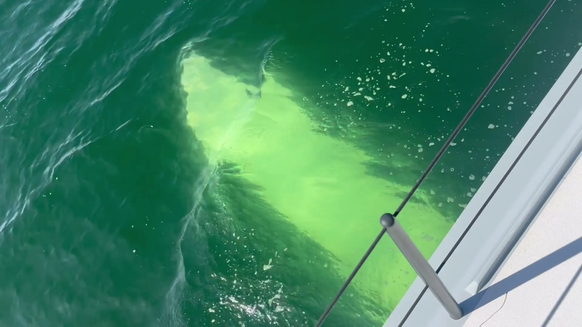
Roughly sixteen feet long and three feet wide, PB72’s curved carbon foil reaches out from the leeward hull. Its case is raked hydraulically, so its angle of attack, and the lift it makes, can be set to any value, at any time.
Below nine knots of wind it stays out of the way. From eleven to thirteen knots it begins to take the load, lifting the yacht from a point well outboard of the leeward hull, about 14 feet (4 m) from her centre of gravity, and cutting the drag of the hulls dramatically. The boat stays almost level as she flies.
The foil can carry the entire boat, but simulation showed the most stable condition is just skimming the water, with the foil carrying 80 to 90% of her weight depending on the waves.
“Unlike the full foilers seen in the America’s Cup, where yachts fly completely free of the water, we deliberately chose a configuration that retains some hull contact.”
02 · Two foils per side
One job
each
No other catamaran carries two foils on each side. On the original Extreme H2O, one C-foil had to do two jobs at once: it was both the daggerboard and the lifting foil. Above about 25 knots it pulled the boat to windward. For PB72, Pat insisted on separating the two forces, over objections that it would be too complicated and too heavy: a centreline daggerboard handles leeway, which frees the lifting foil to be shaped purely for lift.
As boat speed builds, the lifting foil changes rake and the daggerboard retracts. Both are infinitely adjustable, so each carries only as much area as the moment needs.
Why two foils
The lesson of
the first boat
The original Extreme H2O taught Pat the limit of asking one foil to do everything. These two drawings by Ferdinand van West show why PB72 is built differently.
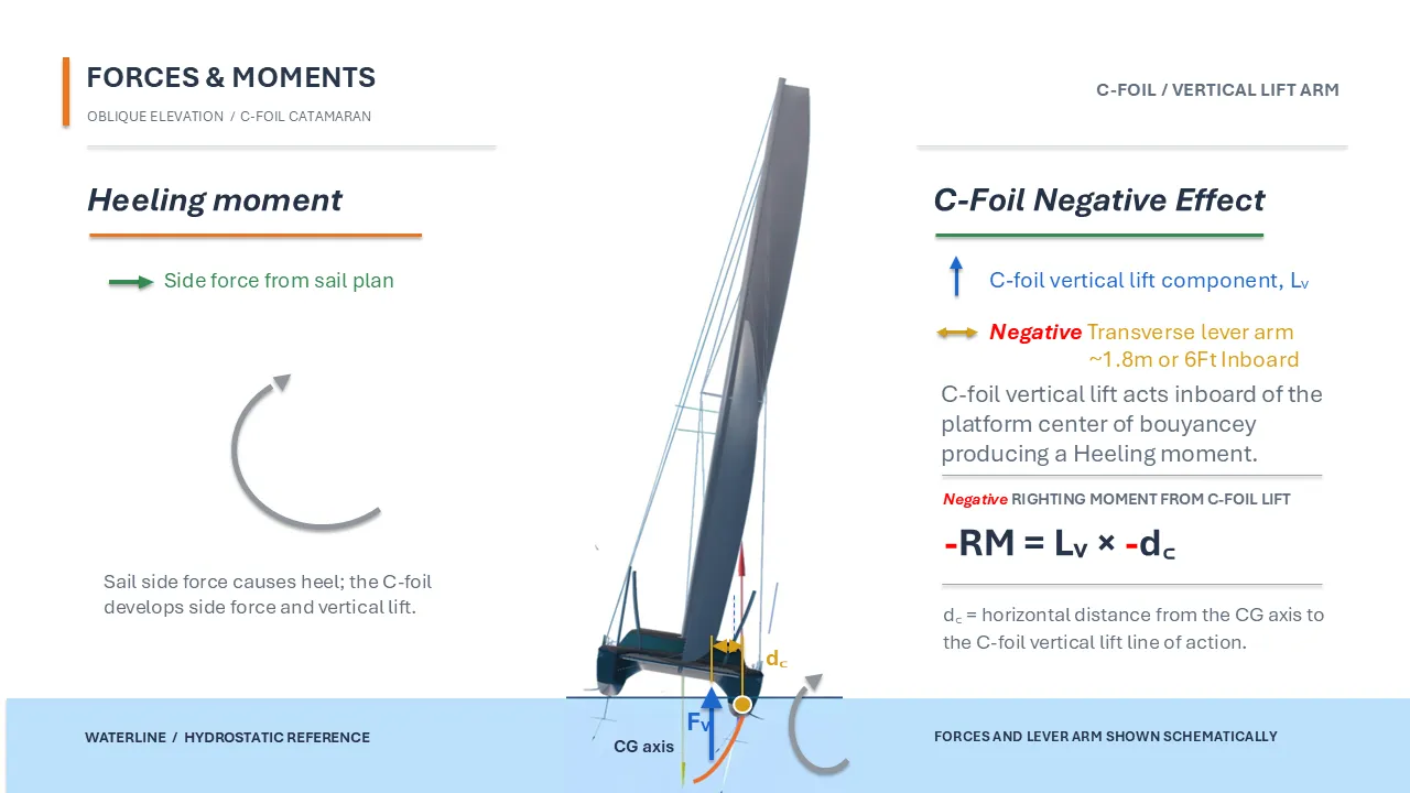
2015 · The original Extreme H2O · C-foil
One C-foil did two jobs: daggerboard and lifting foil. Its lift acted about 6 ft (1.8 m) inboard of the boat’s centre of buoyancy, so instead of helping to hold her upright it actually added to the heel. A negative righting moment.
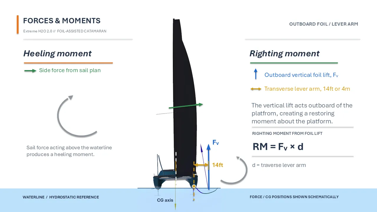
PB72 · Outboard righting-moment foil
PB72 separates the jobs: a daggerboard for leeway, and a lifting foil that reaches out from the leeward hull. Its lift acts about 14 ft (4 m) outboard of her centre of gravity, so every pound of lift pushes her upright. That restoring moment is what lets her carry far more sail, and far more power.
Righting moment = foil lift × lever arm Same principle, opposite results: what matters is which side of the boat the lift acts on.
On the drawings
Where the
foils sit
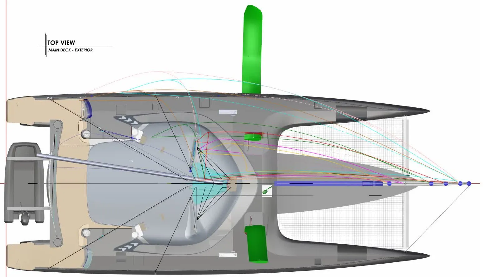
From above, the lime foils sit alongside the cabin, one in each hull. From the front, the leeward foil curves out and down beneath the boat.
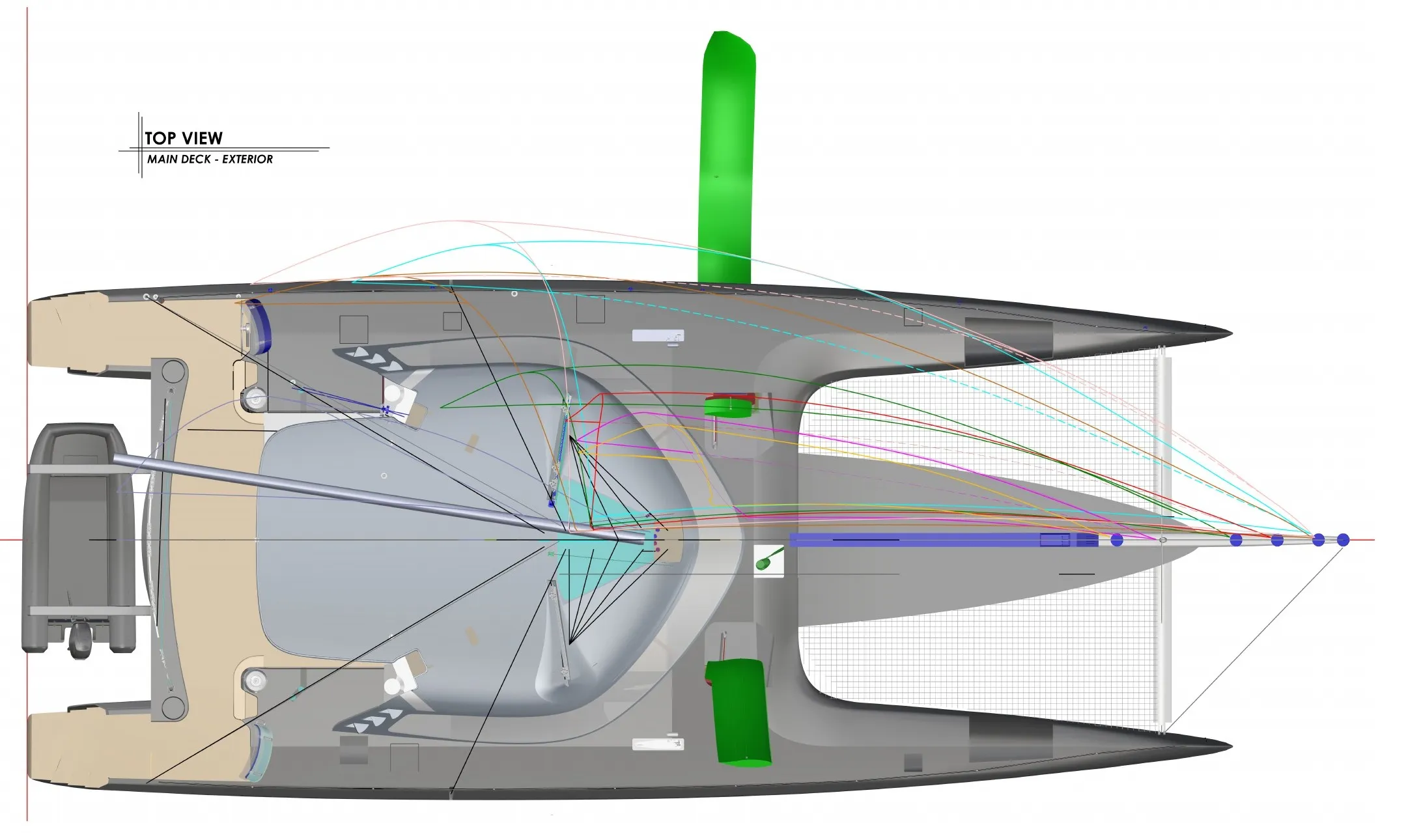
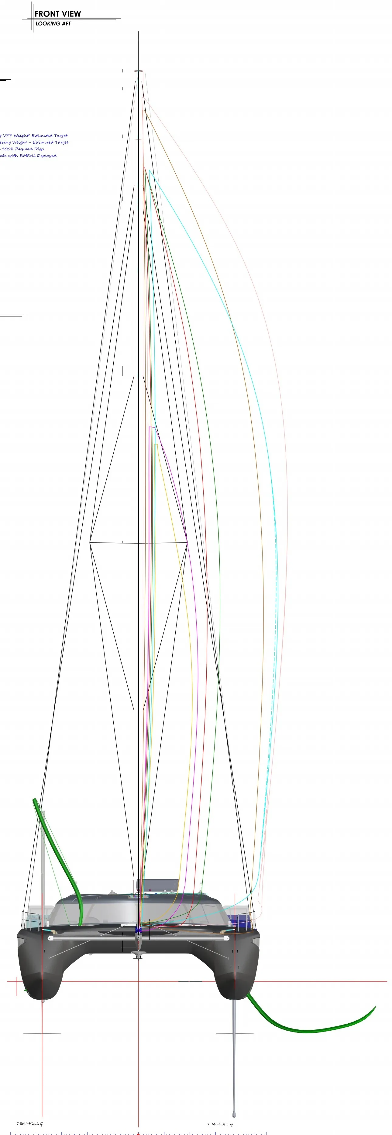
Morrelli & Melvin Design & Engineering · PB72_001 Rev A · 6 August 2022 · Reproduced with permission
03 · Rudders
Pitch,
on demand
Each rudder rakes, and each carries a T-foil about six feet across, so the crew can push the bow up or down independently on each side.
The rudders turn on conical titanium bearings that let each one move fore and aft to bring the bow up or down, adjusting her attitude like an aeroplane. Together with the main foil they give PB72 two continuously adjustable forces that conventional boats simply don’t have.
“With the help of Team New Zealand engineers, they began helping us to design a flight control system.”
04 · Flight control
Built for
fly-by-wire
Right after the last America’s Cup, engineers from Team New Zealand began helping design PB72’s flight-control system, and they remain the partner working on it. The boat is designed and fully built to support it: it will manage the angle of attack of the main foil and the rudder T-foils together, holding ride height and attitude as wind and sea change.
So far, every flight has been sailed with the foils trimmed by hand. Once the foil and wind instruments are fully calibrated during the remaining sea trials, the flight-control system comes online and the boat can be sailed to the numbers her designers predicted.

- Main foil
- ≈ 16 × 3 ft
- T-foils
- ≈ 6 ft
- On each rudder
- Draft, boards down
- 5.31 m
- Draft, foils raised
- 0.65 m
- Shallow anchorages
Two new forces.
Total control.
At the helm · sea trials
Private enquiries
PB72 is in sea trials. Partnerships, racing programs, experiences and charter are discussed personally with our team.
Extreme H2O · Foiling ocean catamaran · Technical specification
PB72 specifications
Morrelli & Melvin · GA PB72_001 Rev A · Persico Marine build spec
- Length overall
- 21.95 m
- 72.0 ft
- Beam
- 9.50 m
- 31.2 ft
- Racing displacement
- ≈ 21.5 t
- As built · VPP targets at 20.3 t
- Mast
- 32.33 m
- Air draft 37 m
- Upwind sail area
- 420 m²
- Main 224 + J1 196
- Fastest upwind
- J3 + main
- Full main 224 + J3 115 m²
- Fastest downwind
- MHO + main
- Full main 224 + MHO 358 m²
- Predicted top speed
- 40+ kn
- VPP
Principal dimensions
- Length overall
- 21.95 m72.0 ft
- Length incl. longeron
- 24.10 m79.1 ft
- Length waterline
- 21.45 m70.4 ft
- Beam overall
- 9.50 m31.2 ft
- Hull centreline spacing
- 7.52 m24.7 ft
- Freeboard
- 2.07 m6.8 ft
- Draft, boards down
- 5.31 m17.4 ft
- Draft, foils raised
- 0.65 m2.1 ft
- Air draft
- 37.00 m121.4 ft
Displacement & stability
- Light displacement
- ≈ 21,000 kgAs built · design 20,500 kg
- Racing displacement
- ≈ 21,500 kgAs built · as sailed in sea trials
- VPP target displacement
- 20,280 kgDesign racing weight used for the polar targets
- Design displacement (mLDC)
- 23,047 kgMaximum load condition
- Max total load (ISO 8666)
- 22,518 kg
- Steady-state sailing RM
- 830 kNmAt full-payload displacement
- Max dynamic RM
- 1,340 kNmRace mode, RMFoil deployed
Rig
- Mast tube length
- 32.33 m106.1 ft
- Mast design rake
- 4°
- P
- 31.285 mReefs: 26.604 · 21.970 · 14.190 m
- E
- 9.678 m
- I (1 · 2 · 3)
- 33.470 · 32.775 · 30.900 m
- I headstay (5 · 6)
- 28.050 · 25.720 m
- J (1 · 2 · 3)
- 12.180 · 11.730 · 10.980 m
- J headstay (5 · 6)
- 8.744 · 8.072 m
- BAD · HBI
- 1.906 · 2.019 m
Sail areas
- Mainsail, full
- 224 m²Reefs: 183 · 144 · 76.8 m²
- J0
- 219 m²
- J1
- 196 m²
- J3
- 115 m²
- J4 / staysail
- 87.3 m²
- FRO
- 304 m²
- MHO
- 358 m²
- A1
- 365 m²
- Fastest upwind setup
- J3 + full mainJ1 in marginal upwind conditions, 13–14 kn: partial foiling
- Fastest downwind setup
- MHO + full main
Foils & flight control
- Righting-moment foil
- ≈ 16 × 3 ftCurved carbon foil in a hydraulically raked case
- Daggerboards
- Centreline, per hullIndependent of the lifting foil
- Rudders
- Raking, T-foilConical titanium bearings · ≈ 6 ft T-foils
- Flight control
- Designed for fly-by-wireFoil lift and rudder-elevator control; programmed after sea trials
Construction & class
- Hull
- Carbon fibreFoam & Nomex sandwich
- Superstructure
- Carbon fibreFoam & Nomex sandwich
- Classification
- ISO 12215-7 Cat. ASER1 multihull · highest category, sport boat
- Propulsion
- 2 × 35 kW electricTorqeedo
Rig & deck hardware
- Mast
- Carbon rotating wing mastSupplied by SSNZ · single spreader, double diamond, running backstays
- Primary winches
- 4 × Harken 1125.3
- Secondary winches
- 2 × Harken 65.3 ST
- Windlass
- Lewmar V6 hydraulic
Propulsion & power
- Main engines
- 2 × Torqeedo electric25 kW continuous · 35 kW max each
- Drive
- Shaft driveStrut and P-bracket · Gori GP20 folding propellers
- Motoring speed
- 9.2 kn max7.5 kn cruise (estimated)
- Generators
- 2 × 20 kW Fischer Panda
- Propulsion battery
- 40 kWh lithium-ionBMW i3 cells
- Solar
- 2 kWPanels on the coachroof
- Electrical
- 120 V and 240 V AC400 V DC charging & hydraulic bus · 24 V domestic · Empirbus digital switching
Tankage
- Fuel
- 2 × 550 L
- Fresh water
- 2 × 450 LPlus 70 L drinking water
- Watermaker
- Schenker Modular Zen 50
- Black water
- 2 × 220 L
Comfort & systems
- Air conditioning
- 64,000 BTU/hTermodinamica
- Galley
- Gaggenau hobsPizza oven · Miele microwave · Miele coffee machine
- Refrigeration
- 3 × 172 L fridgesPlus Frigonautica freezer
- Navigation
- B&G / Simrad
- Communications
- VHF · 5G · SatcomSatellite broadband
- Steering
- Outside helms + inside helmFly-by-wire steering at the inside helm station
Performance
- Predicted top speed
- 40+ knPolar peak 40.7 kn
- Foiling onset
- 11–13 kn TWSDepending on sail set
- Upwind, 13 kn of wind
- ≈ 24 kn
- Downwind, 14 kn of wind
- ≈ 31 kn
- Crew
- 4 per watchTo sail her fast; two watches for round-the-clock ocean racing
Velocity prediction program, partially validated in sea trials.
Design & build
- Naval architecture
- Morrelli & MelvinNewport Beach, California
- Lead designer
- Ferdinand van WestThen at Morrelli & Melvin; now Van West Naval Architecture
- Interior architecture
- Design Unlimited
- Builder
- Persico MarineItaly
- Flight control
- Team New Zealand engineers
- General arrangement
- PB72_001 · Rev A6 August 2022
Figures from the Morrelli & Melvin general arrangement (PB72_001, Rev A, August 2022) and the Persico Marine build specification. Displacements are approximate as-built figures from Ferdinand van West (2026); righting moments are design estimates; performance figures are VPP predictions, calculated at the 20,280 kg design racing displacement.
Every cell is a predicted boat speed from the velocity prediction program. The circled cells are the targets PB72 has already hit in her first sea trials, with the foils still trimmed by hand. Each one came in on target.
| Wind angleTrue wind (kn) | 5 | 6 | 7 | 8 | 9 | 10 | 11 | 12 | 13 | 14 | 15 | 16 | 18 | 20 | 22 | 24 |
|---|---|---|---|---|---|---|---|---|---|---|---|---|---|---|---|---|
| 45° | 7.6 | 8.4 | 9.1 | 9.8 | 10.4 | 11.3 | 12.6 | 13.6 | 14.4 | 15.1 | 16.0 | 17.4 | 20.5 | 23.4 | 24.0 | 23.7 |
| 50° | 8.0 | 8.9 | 9.7 | 10.5 | 11.2 | 12.8 | 14.3 | 15.1 | 16.3 | 17.6 | 19.5 | 21.6 | 27.1 | 27.5 | 27.0 | 26.5 |
| 55° | 8.4 | 9.3 | 10.2 | 11.2 | 12.2 | 14.2 | 15.7 | 17.0 | 18.8 | 20.8 | 23.4 | 27.6 | 30.1 | 30.2 | 29.5 | 28.9 |
| 60° | 8.8 | 9.7 | 10.7 | 11.8 | 13.2 | 15.3 | 17.1 | 19.3 | 21.5 | 26.1 | 28.6 | 30.2 | 32.4 | 32.3 | 31.6 | 30.9 |
| 65° | 9.1 | 10.1 | 11.2 | 12.3 | 14.3 | 16.4 | 19.1 | 21.5 | 26.1 | 29.0 | 30.8 | 32.2 | 34.3 | 34.2 | 33.4 | 32.4 |
| 70° | 9.3 | 10.4 | 11.5 | 12.7 | 14.9 | 17.9 | 20.9 | 24.1 | 28.6 | 30.8 | 32.4 | 33.8 | 35.8 | 35.7 | 34.8 | 32.3 |
| 75° | 9.5 | 10.6 | 11.8 | 13.1 | 15.4 | 19.4 | 22.6 | 27.3 | 30.2 | 32.2 | 33.7 | 35.1 | 37.1 | 37.1 | 36.2 | 34.0 |
| 80° | 9.7 | 11.0 | 12.3 | 13.9 | 15.8 | 20.6 | 25.1 | 28.7 | 31.4 | 33.2 | 34.7 | 36.1 | 38.1 | 38.2 | 37.3 | 36.2 |
| 85° | 9.8 | 11.2 | 12.6 | 14.2 | 16.2 | 21.3 | 26.9 | 29.8 | 32.2 | 34.0 | 35.5 | 36.9 | 39.0 | 39.1 | 38.3 | 37.5 |
| 90° | 9.9 | 11.3 | 12.7 | 14.4 | 16.4 | 21.5 | 27.7 | 31.5 | 33.5 | 35.1 | 36.3 | 37.5 | 39.6 | 39.8 | 39.1 | 38.7 |
| 95° | 9.9 | 11.3 | 12.8 | 14.4 | 16.5 | 21.0 | 28.7 | 31.7 | 33.9 | 35.5 | 36.8 | 37.9 | 40.0 | 40.3 | 39.8 | 39.5 |
| 100° | 9.9 | 11.3 | 12.7 | 14.2 | 16.3 | 22.3 | 28.8 | 31.7 | 34.2 | 35.8 | 37.0 | 38.1 | 40.3 | 40.6 | 40.3 | 40.0 |
| 105° | 9.8 | 11.1 | 12.5 | 14.0 | 15.7 | 21.0 | 28.3 | 31.4 | 34.0 | 35.8 | 37.1 | 38.2 | 40.3 | 40.7 | 40.5 | 40.3 |
| 110° | 9.7 | 10.9 | 12.2 | 13.6 | 15.1 | 17.7 | 26.8 | 31.0 | 33.3 | 35.5 | 37.0 | 38.2 | 40.2 | 40.7 | 40.6 | 40.4 |
| 115° | 9.5 | 10.6 | 11.8 | 13.1 | 14.5 | 16.5 | 19.9 | 30.0 | 32.6 | 34.8 | 36.6 | 37.9 | 40.0 | 40.3 | 40.4 | 40.1 |
| 120° | 9.2 | 10.3 | 11.4 | 12.5 | 13.7 | 14.9 | 17.4 | 25.8 | 31.8 | 34.0 | 35.6 | 37.4 | 39.6 | 40.0 | 40.0 | 39.6 |
| 125° | 8.9 | 9.9 | 10.8 | 11.6 | 12.4 | 13.5 | 14.7 | 16.3 | 29.7 | 32.9 | 34.9 | 36.4 | 39.0 | 39.6 | 39.6 | 39.1 |
| 130° | 8.5 | 9.4 | 10.0 | 10.8 | 11.9 | 13.1 | 14.3 | 15.5 | 17.1 | 18.0 | 33.4 | 35.4 | 38.1 | 38.9 | 39.1 | 38.6 |
| 135° | 8.2 | 8.7 | 9.5 | 10.5 | 11.5 | 12.6 | 13.7 | 14.8 | 16.2 | 17.3 | 18.4 | 20.0 | 37.0 | 38.0 | 38.2 | 37.7 |
| 140° | 7.6 | 8.2 | 9.1 | 9.9 | 10.9 | 11.9 | 12.9 | 14.0 | 15.2 | 16.4 | 17.7 | 19.1 | 22.1 | 35.4 | 30.7 | 35.0 |
Predicted speeds from the velocity prediction program. Sea-trial targets achieved with manual foil trim; the automatic flight-control system comes online after calibration.
- VPP targets calculated at
- 20,280 kg
- Design racing displacement
- Sea trials sailed at
- ≈ 21,500 kg
- As-built racing displacement
Every circled target was reached with the boat about 1.2 tonnes heavier than the weight the predictions assume.